Space rated encoders and position sensors

MACCON designs and manufactures space-qualified linear or rotary encoders based on various physical principles. These are discussed in detail below. Depending upon the application, a compromise must be reached between weight, cost, dimensional requirements and hardening against the space environment. In addition, the choie of encoder might be influenced by other design goals such example redundancy and other design constraints such as the capabilities of the motor drive electronics.

The space-qualified encoders from our portfolio are based on the following physical principles:

  • Magnetoresistive effect
  • Capacitance
  • Inductance
  • Optical
  • Magnetic

Please keep reading to learn more, or, contact us to discuss your requirements.

Nonius-Ring with scanning head according to the magnetoresistive principle

This magnetoresistive (MR) technology is ideal for implementing read-head redundancy. The MACCON MR-Encoder has been developed for the measurement of absolute position in extreme physical environments with a resolution up to 19 Bits. It is especially suited for use in Aircraft and Space and is undergoing full space-rating qualification to ESA standards.

Summary of the benefits of the MR-encoder:

  • Fully passive with no integrated electronics, based on the GMR effect (Giant magnetoresistance) Only potentiometers, resolvers and Inductosyn© are comparable in terms of reliability
  • Due to its simplicity and passive structure the MR encoder is highly robust and reliable
  • Encoder rings can be scaled to fit the application; hollow-shaft designs are easily implemented
  • Highly flexible with regard to positioning and mounting of reading head(s)
  • Accurate, light and low power consumption
  • Measurement is absolute over 360° (temporary position loss is immediately corrected) using the Nonius principle.
  • Incremental measurement requires one tooth-ring only
  • Duplication of reading heads allows direct implementation of multiple redundancy
  • Insensitive to environmental influences, such as magnetic and radiation fields, as well as to temperature and shock
  • Very high signal bandwidth (>> 1 MHz), ideal for precise position measurement at high speed, excellent servo-loop response

Please download the datasheet on the right-hand side, for more information, or contact us to discuss your requirements.

Do you have technical questions or need a quote?

Contact us today to talk to an experienced MACCON engineer!

Inductosyn Position Transducers

Our Inductosyn encoders, which have proven themselves for 60 years in space, in aircraft and on ships, are suitable for harsh environments and high measuring accuracy.

Technology:

  •  Both rotary and linear versions
  •  Operating principle: inductive (according to the resolver principle)
  •  High pole count, therefore much more accurate than resolvers (typically <10", independent of temperature)
  •  Electrical interface similar to resolver: sine excitation at approx. 10kHz, evaluation via R/D converter
  •  Incremental or absolute angle or displacement measurement
  •  Can be mounted directly on the axis of rotation
  •  Optimum adaptation possibilities to different environmental conditions due to different substrate materials (steel, aluminium, glass, ceramics etc.)
  •  Can be used at very low to very high temperatures and/or in ultra-high vacuum at very high pressure
  •  Non-contact design, i.e. no wear (no lubrication or adjustment required), extremely reliable and durable

Do you have technical questions or need a quote?

Contact us today to talk to an experienced MACCON engineer!

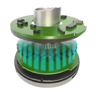
Capacitive Encoder

The main technical and economic benefits of the electric / capacitive encoder technology can be summarized as follows:

  • No glass disc, no LED light source, so that eliminates possible points of failure
  • Generous mounting tolerances
  • Very low weight, inertia, and profile (=<10mm)
  • Ring shaped, hollow shaft with a wide range of diameters
  • Absolute position output over 360° rotation range
  • Precision to 0.001° in selected models
  • Default operation range from -40°C to +85°C
  • Dual and triple redundancy options
  • No magnetic signature
  • High tolerance to condensation and contaminants
  • Insensitivity to EMI/RFI and magnetic fields
  • High customizability
  • Low power consumption
  • Ultra-high-speed options
  • Wide variety of position feedback protocols

Do you have technical questions or need a quote?

Contact us today to talk to an experienced MACCON engineer!

Space-rated wound and reluctance resolvers

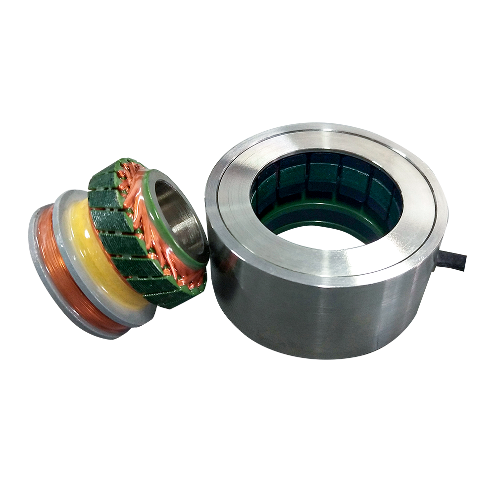
We also offer the well-known wound resolver as a space-rated variant (see picture on the right). Less well known, however, is the reluctance resolver, which has certain advantages and disadvantages over the wound resolver. See table further below for a comparison of the two technologies.

The variable reluctance resolver (VRR) consists of a rotor and stator (see picture on the right). The stator consists of insulated copper wire windings (primary and secondary) wound on laminated silicon steel. The rotor is oval-shaped and consists only of laminated silicon steel. The oval shape of the resolver causes a change in reluctance when the rotor revolves inside the stator. This change in reluctance can be used to detect the rotor angle. In contrast to conventional resolvers (rotor and stator both wound), reluctance resolvers have both primary and secondary windings on the stator and do not need a winding in the rotor. This offers many advantages in terms of cost, mass and space requirements. The variable reluctance resolver weighs less, has a shorter axial length and costs less than a conventional resolver.

We manufacture our reluctance resolvers in-house using ESA-certified materials (e.g. a low outgassing potting compound for the stator winding, nickel-plating of stator/rotor lamination stack). We can also offer a redundant stator winding if required. We offer resolvers with different inner and outer diameters.

Do you have technical questions or need a quote?

Contact us today to talk to an experienced MACCON engineer!

Comparison of wound and reluctance resolvers

TopicWound ResolverReluctance Resolver
StatorIron core with windingIron core with winding
RotorIron core with windingLamination stack with no winding
Minimum amount of pole-pairs1 Pole-pair2 Pole-pairs
Type of feedbackAbsolute over 360° for 1 pole-pairNot absolute over 360°
as minimum 2 pole-pairs
Axial LengthLongerShorter
ReliabilityHighHigher, as rotor has no winding.
Mechanical accuracy
(1 mechanical cycle = 360°)
±10 arcmin for 1 pole-pair
±8 arcmin for 2 pole-pairs
±4 arcmin for 4 pole-pairs
±2 arcmin for 8 pole-pairs
±0,5 arcmin for 16 pole-pairs
±0,33 arcmin for 32 pole-pairs
±0,16 arcmin for 64 pole-pairs

Note: the higher the number of
pole-pairs, the higher the accuracy.
However the maximum achievable
speed will be limited due to the
the bandwidth of the drive electronics.
±1° for 2 pole-pairs

The higher the pole-pair count, the
better the accuracy.
Rotor throughbore
("rotor inside diameter")

As a rule-of-thumb:
1-4 pole-pairs, throughbore: 6mm-20mm
8-16 pole-pairs, throughbore: 20mm-30mm
32 pole-pairs, throughbore: 40mm
64 pole-pairs, throughbore: 80mm

Larger throughbore possible, on a
project-specific basis.


In general, the throughbore of
reluctance resolvers is larger
than that of wound resolvers.

CostHigherLower
Application

- Motor commutation
- Speed control
- Position control

- Motor commutation
- Speed control


Hall-Effect-Sensors

These are mainly directly integrated in the motor windings and are only used for commutation or can be used for simple speed or position control tasks.

Do you have technical questions or need a quote?

Contact us today to talk to an experienced MACCON engineer!