Sensorless motor control is attractive for situations where the use of encoders, angle measurement systems and Hall sensors as feedback from motors is not an option. This could be the case for several reasons:

  • The speed is too high and cannot be handled by the encoder
  • The speed is so high that the Hall sensor feedback is no longer properly synchronized
  • Even if the speeds are lower, the encoder and/or Hall sensors are undesirable, as they represent potential points of failure.
  • Last but not least: if the motor is operating in a harsh environment (e.g. PMSM kit motor working driving a fuel pump, submerged in the fuel), it may not be possible to have encoder or Hall sensor electronics in the motor.

Sensorless control is usually used for speed control of PMSM/BLDC motors. As the motor does not need the encoder and/or Hall sensors, space is saved, cost is saved and complexity as well as potential points of failure are eliminated.

Significant features of the converters

  • sensorless control
  • no output filter needed
  • minimum motor losses
  • fast commissioning

Drive electronics and servodrives for sensorless control

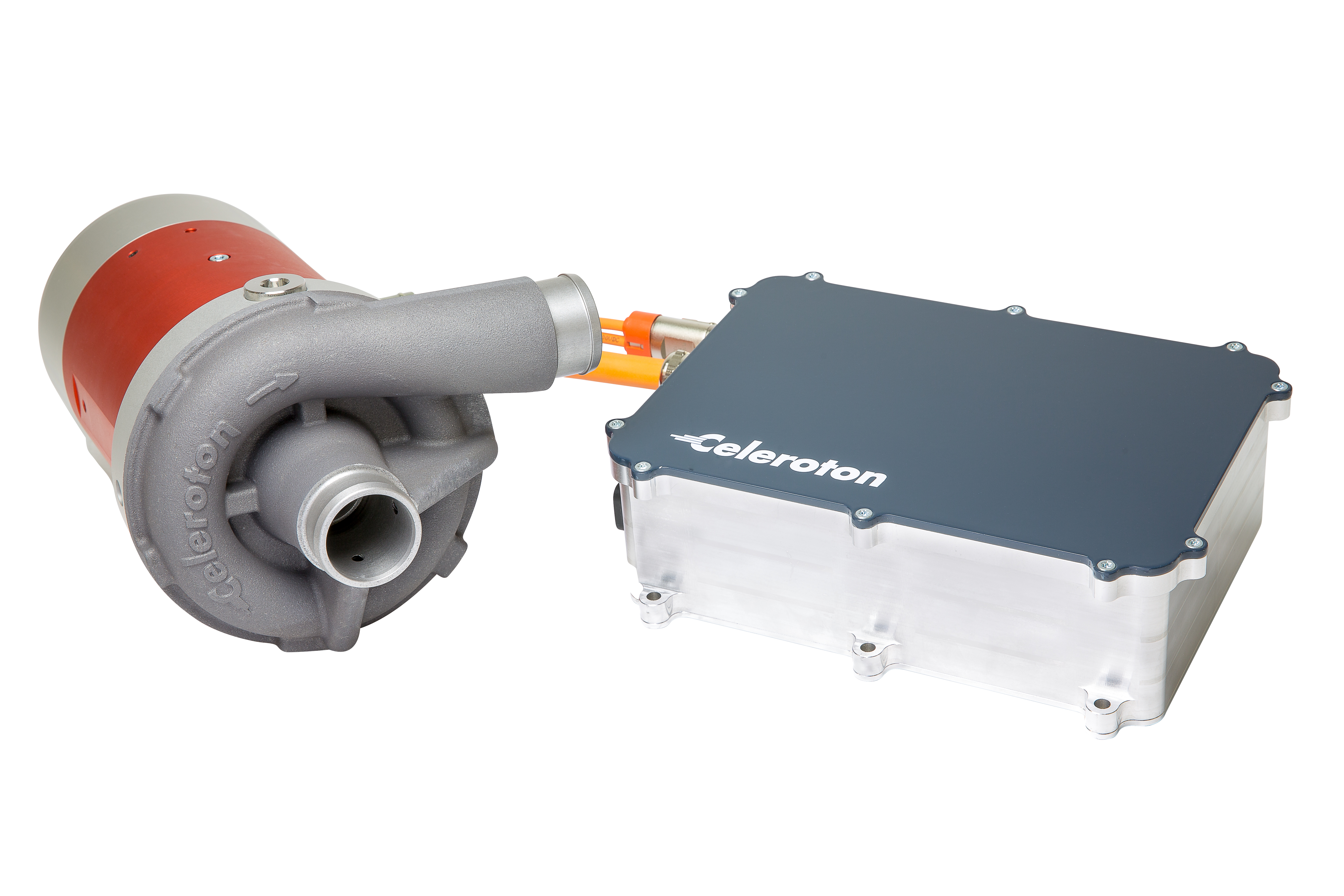
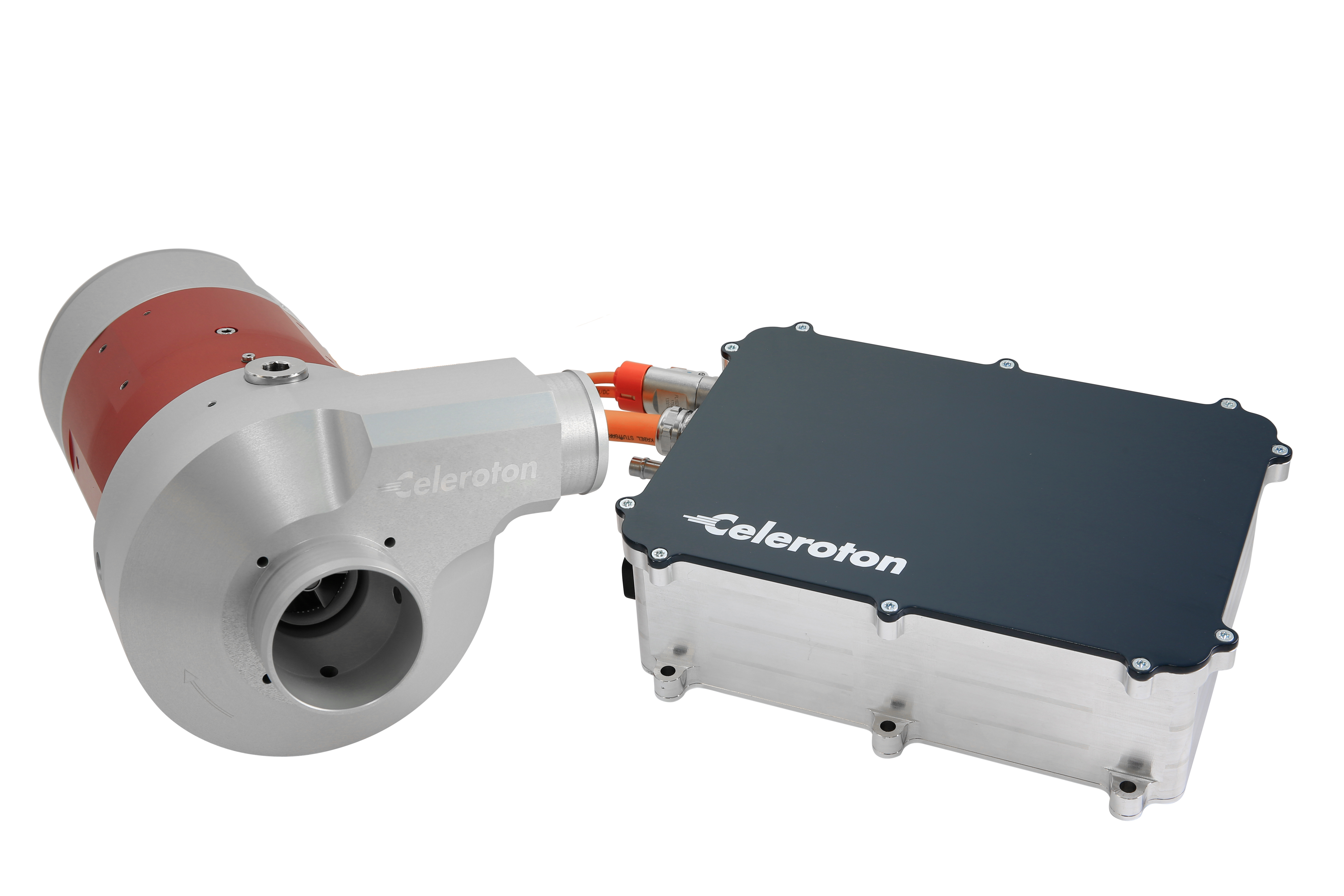
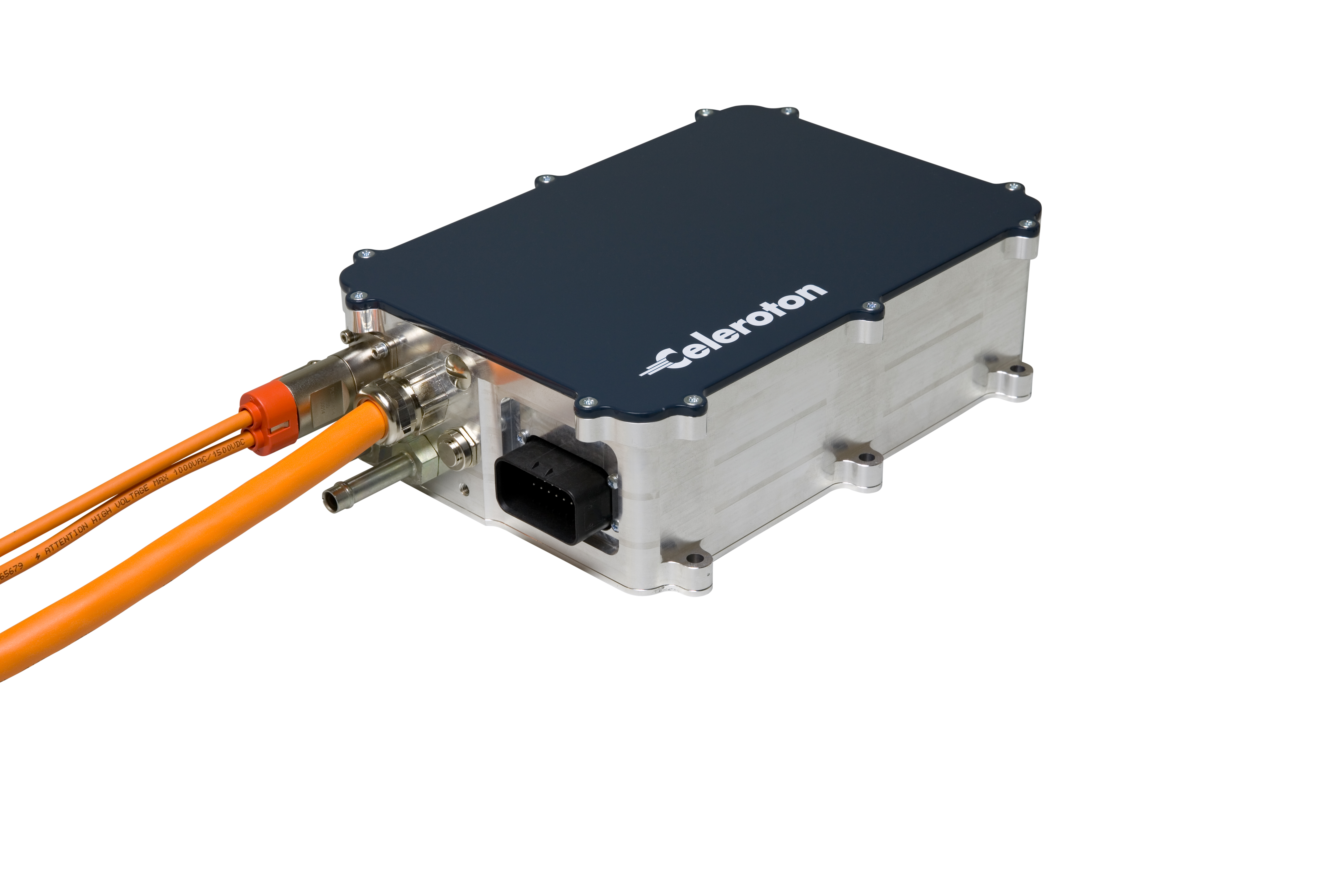
Sensorless control – from standstill to 1 million rpm. Our ultra high-speed servodrives allow sensorless control of permanent magnetic synchronous machines (PMSM) and brushless DC motors (BLDC). This means that no encoder and/or hall sensors are required as feedback devices.

The tuning of the modulation and control systems of our motors and turbo compressors, or of your electric motor, guarantees the highest converter operating efficiency and reduced motor losses. In the same converter we can operate with both pulse-width modulation (PWM), with varying switching frequencies, and pulse-amplitude modulation (PAM). Thanks to PAM technology, the output filter between Motor and Converter can be eliminated.

A specially developed sensorless control method allows for complete speed control without an encoder or Hall sensors. Auto tuning, automatic control parameterization and support from our engineers results in swift installation and commissioning.

Do you have technical questions or need a quote?

Contact us today to talk to an experienced MACCON engineer!

TypeOutput
power
RangeInput
voltage
Output
voltage
WeightDatasheet
CC-32-100100 W0 - 80.000 U/min24 - 32 VDC0 - 30 V0.02 kg
CC-75-500500 W0 - 1.000.000 U/min24 - 75 VDC0 - 0.95 Uin1 kg
CC-100-10001.000 W0 - 500.000 U/min24 - 100 VDC0 - 93 V0,28 kg
CC-120-10001.000 W0 - 500.000 U/min40 - 120 VDC0 - 100 V1,4 kg
CC-230-35003.500 W0 - 500.000 U/min110 - 230 VAC0 - 360 V4,5 kg
CC-400-1200012.000 W0 - 180.000 U/min200 - 420 VDC0 - 400 V12 kg
CC-550-75007.500 W0 - 300.000 U/min100 - 550 VDC0 - 500 V5,4 kg
CC-AMB375 VA -
1.500 VA
0 - 500.000 U/min24 - 75 VDC0 - 0,95 Uin2,25 kg

Additional solutions

We have other solutions in our portfolio which are not shown on the website. We also develop customer-specific solutions. Please contact us, to discuss your technical requirements. You can find our contact details here.


The different methods of sensorless control

For the control of PMSM and BLDC motors, the rotor angle must be detectable. Normally, this is detected by means of Hall sensors or encoders. The goal of sensorless control is to completely eliminate the need for sensors in the motor. This has several advantages. Particularly in compact motors, the installation space requirement and the number of connecting cables and plugs are reduced. Since there is one less electronic component in the motor without a rotor angle sensor, the reliability of the servo system also increases.

Meanwhile, three important methods exist to enable sensorless control of motors.

  • observer-based control
  • zero crossing detection
  • Measurement of the rotor angle-dependent inductance

Zero crossing detection detects when the regenerative voltage induced in the motor changes polarity. In the Oberver method, an observer runs along (real-time observation of the motor system equations). By comparing the expected motor state with the actual sensed values, the rotor position and speed can be calculated. Inductance method: the inductance of a motor changes depending on the rotor angular position. When comparing the transverse inductance and the longitudinal inductance, the rotor angle can be calculated.


Abstract

Depending on the application, we combine the different methods of sensorless control to achieve the optimum result. Often customers send us their engine for a lab test to make sure your load cycle is achievable. Contact us to discuss your application.

Do you have technical questions or need a quote?

Contact us today to talk to an experienced MACCON engineer!